
Metalworking
What have I been doing with my Sherline CNC mill system? Well, bowhunting season wiped out 3 months of my spare time... but I'm back on it now and you may find this interesting. Keep in mind I am completely new to machining...
I'm writing my own CAD software for this... I decided I want something I can just keep adding functionality to as problems come up. Maybe there's some way to do most of what I want in BobCAD, but I had problems understanding how to make even simple parts with the v18 trial I downloaded without hours of tinkering. I was very uncertain about how much was just my lack of understanding and how much was just lack of functionality. I didn't want to spend that much money and just hope the functionality was there. The lower-priced or shareware/freeware packages I tried were so horrible I wasn't going to take anything for granted.
The funny thing is I just bought an expensive math program to help me solve equations for this CNC software's algorithms... If I spent a little more and I could have bought BobCAD... but now I'm hooked on writing my own stuff.
Here are a few test parts I have cut:
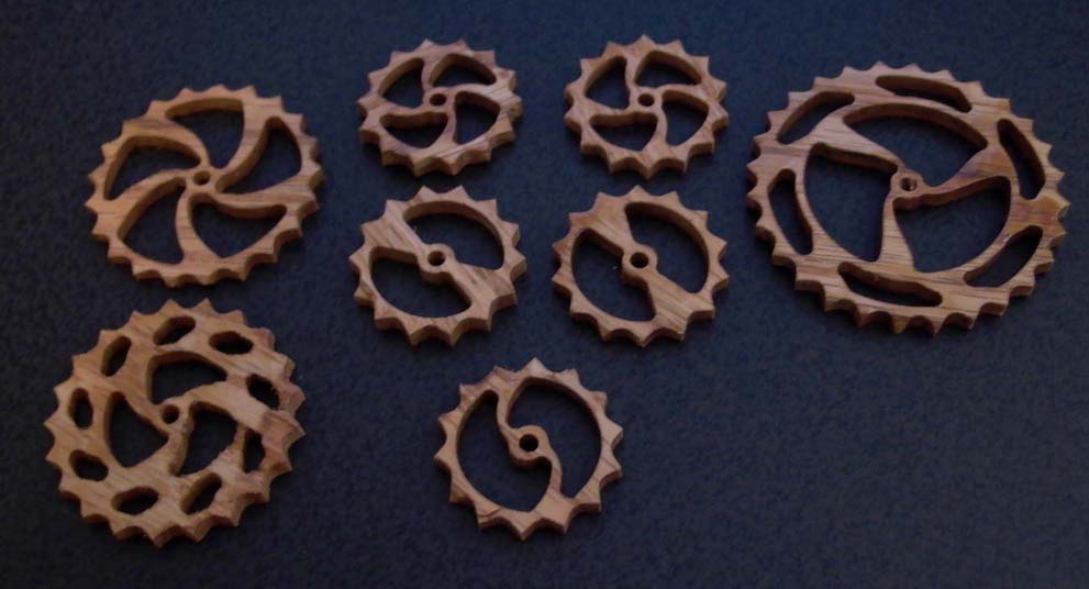
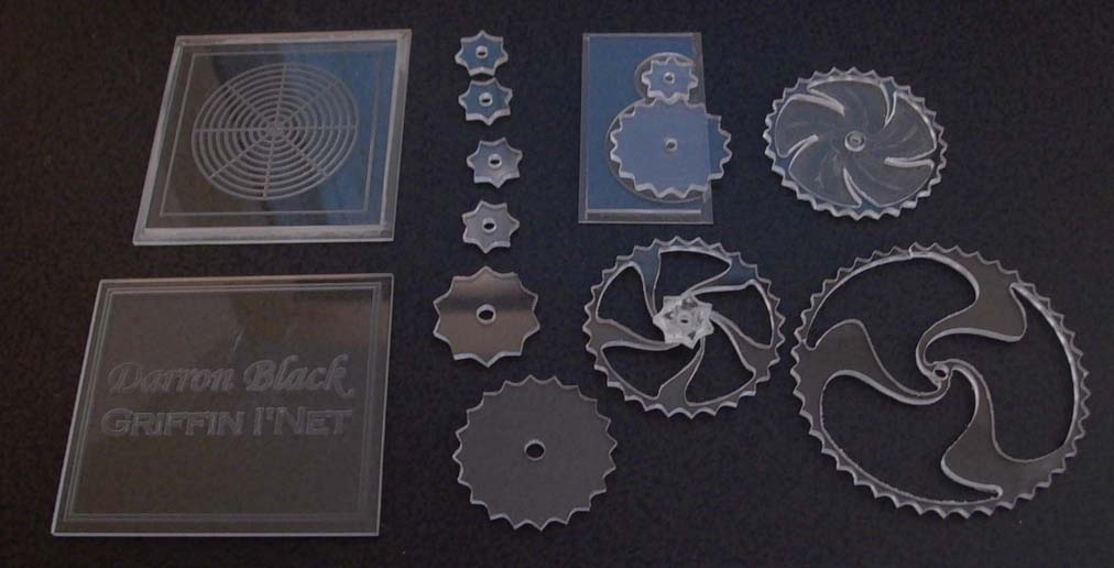
They're not functional, just fun. Why not metal? Well, early on I figured out that the leftover plexiglass I used to build a box for the mill is much cheaper than metal to play with. Wood and plastic are cheaper, easier, and less stressful to learn on. At first, I was terrified of destroying the mill with a typo in NC code. :)
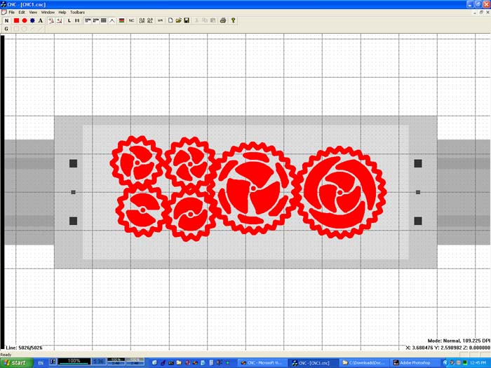
My first long-term project goal is to make a mostly flat wall clock in wood. The idea is for all the gears to be exposed, lying as spead out and flat as possible. Here's a screenshot of some test gears in my software:
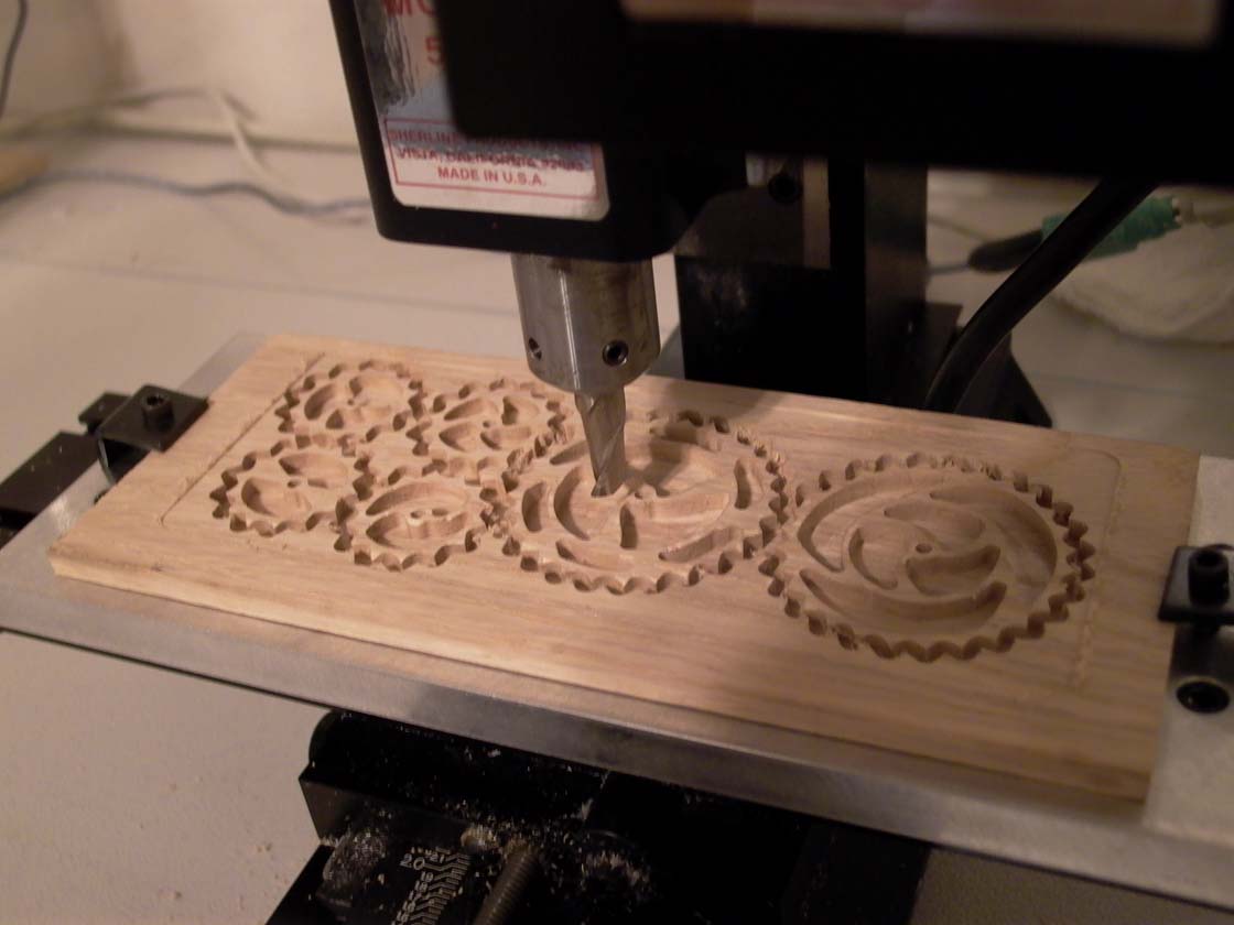
Here are the results on the mill:
Just in case you're interested in the properties page for a gear object...
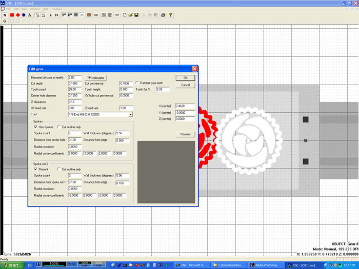
I like seeing parts of the screen exactly the size they will be (from experimentation, 109.2 DPI on my laptop screen is perfect). You can see the gears in a shaded work area which represents the 'safe' zone given my equipment. Under that is the mill tooling plate, and the mill table itself.
The screenshots actually show the cut-out section. The gear object algorithm was the first thing I did... and the software wasn't sophisticated enough at that point to take an arbitrary outline and figure out how to cut it out. So, the algorithm directly calculated the cut path only, and by displaying that I could see what was left. The screen always shows exactly what will be cut... the drawing process itself is similar to the EMC backplot, in that it uses the NC code itself to draw tool paths. For clarity, it just doesn't show anything with Z > 0. The black progress bar on the left side with "Line 5026/5026" next to it tells you this is what the final piece should be. You can grab the black progress bar and scroll it up and down to see how it is going to be cut it out. The NC code is 5000 lines long because the spokes are first approximated into very very small lines, and are then duplicated inside to cut the pockets. (cutting more than the outline is not necessary for the final part, but it looks a lot better on the screen).
My current short-term project goal (they help me develop the software and my machining knowledge towards the clock project) is to make a chinese chess set. My girlfriend is chinese, and her parents are visiting from China for a few months. I figured it would be a nice gift. Anyway, here is a screenshot of one of the four pages of chess pieces:
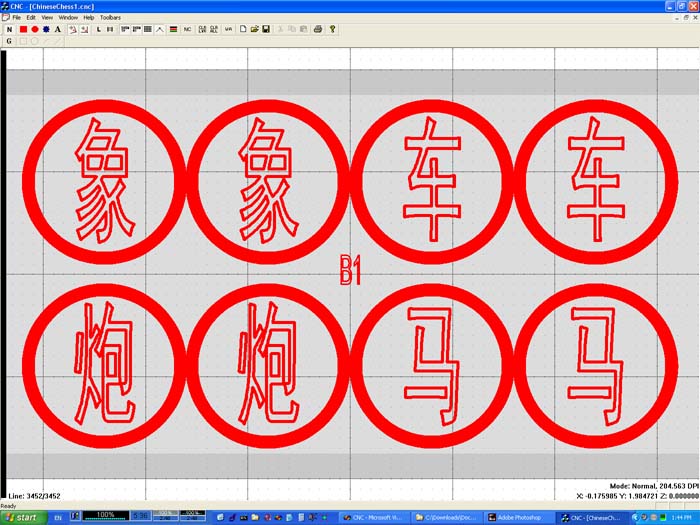
I haven't cut them out yet because my program cannot currently cut out the inside of the text letters. I've cut a single piece, but the rough inside of the outlines made it look bad after my girlfriend painted it. (No, it wasn't her paint job!) I could draw tool path lines inside the letters manually and do it, but I want the program smart enough to cut out arbitrary pocket shapes for me.
One really interesting bit (to me, anyway) with the chess set is going to be the cover of the box. I want two chinese characters for Elephant Game (the chinese words for chinese chess) to be cut into the cover in light hardwood inset into a dark hardwood. In order to do this, the border of the chinese characters must be modified so that no corner is taken too sharply for the given tool radius. I've got a "Round to tool radius" algorithm in the works... this screenshot is of that.
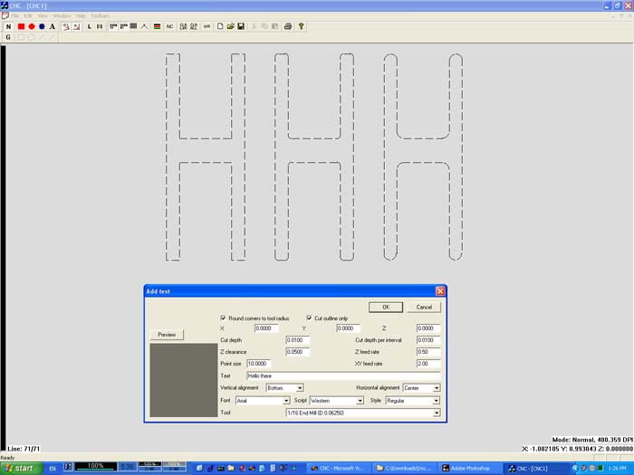
It's incomplete... I need to write the algorithms for correcting line-arc and arc-arc vertexes... so simple letters like these are all it does correctly now.
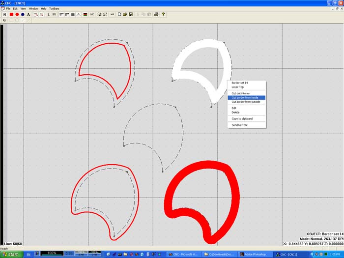
Last, I'll throw in this screenshot... which shows various ways to cut a shape out with a 1/8" end mill. The thinner red lines are just there to show the tool path.
Anyway... I've got a -long- way to go with the software, but I decided to show you where I'm at.
